Project 07 · AME 485 · Aerospace Structures I
Aerospace Structures I — Analysis Projects
AME 485 · Aerospace Structures I · University of Southern California
Course
AME 485 — Aerospace Structures I
Projects
5 Assignments + Midterm
Primary Tool
ANSYS Mechanical
Level
Undergraduate (B.S. Aerospace)
University
USC Viterbi
Jump to Project
Satellite Structure FEA — 10g Launch Loads
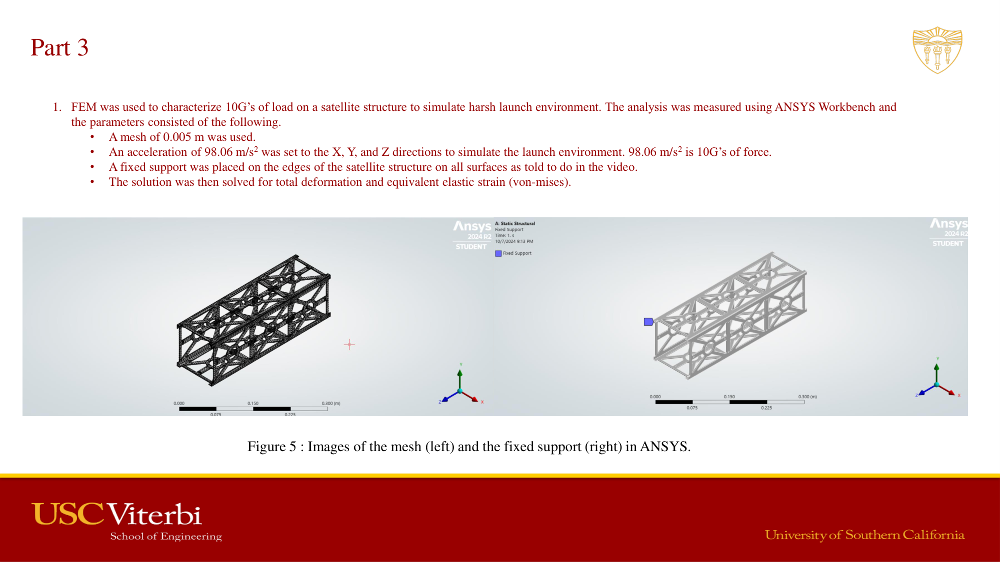
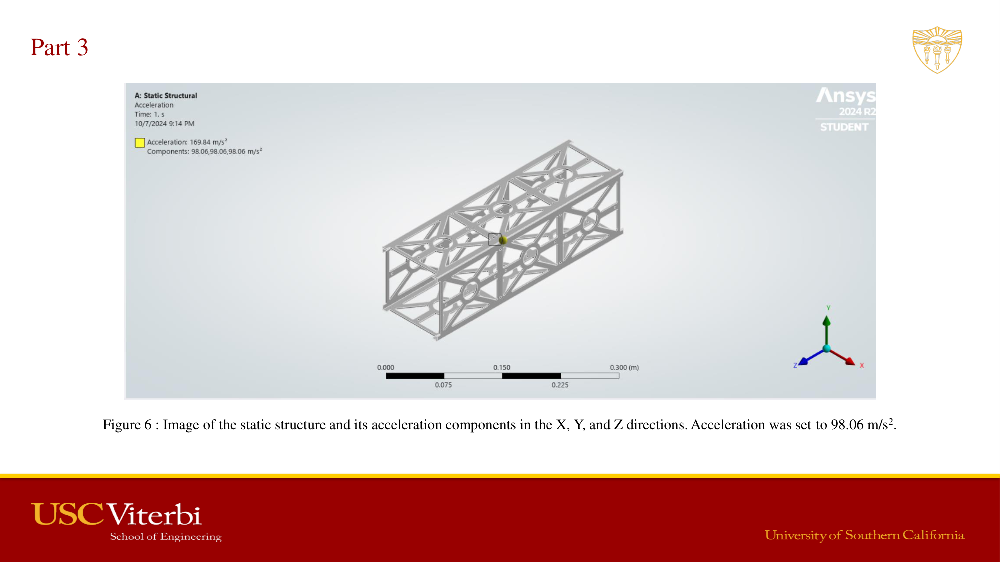
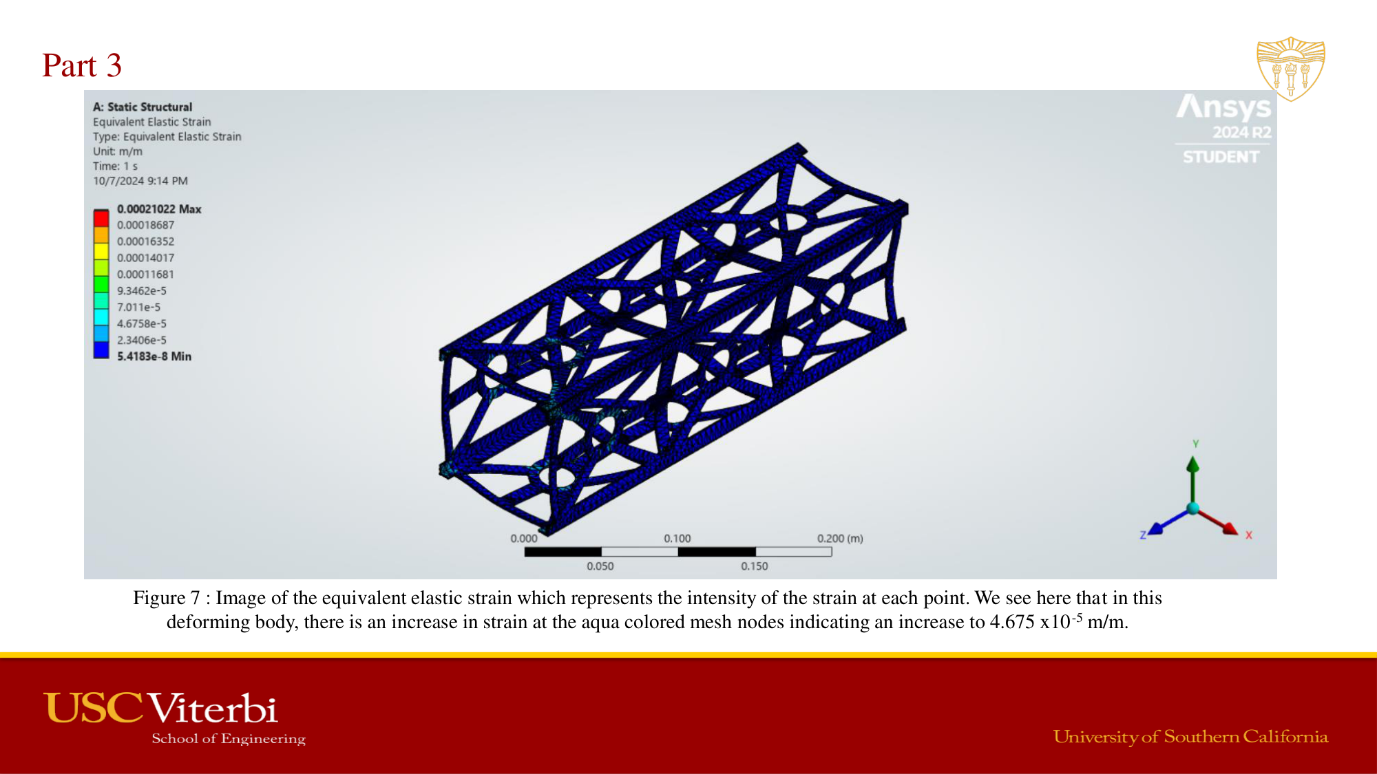
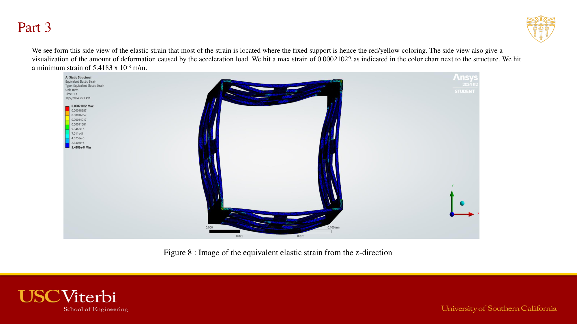
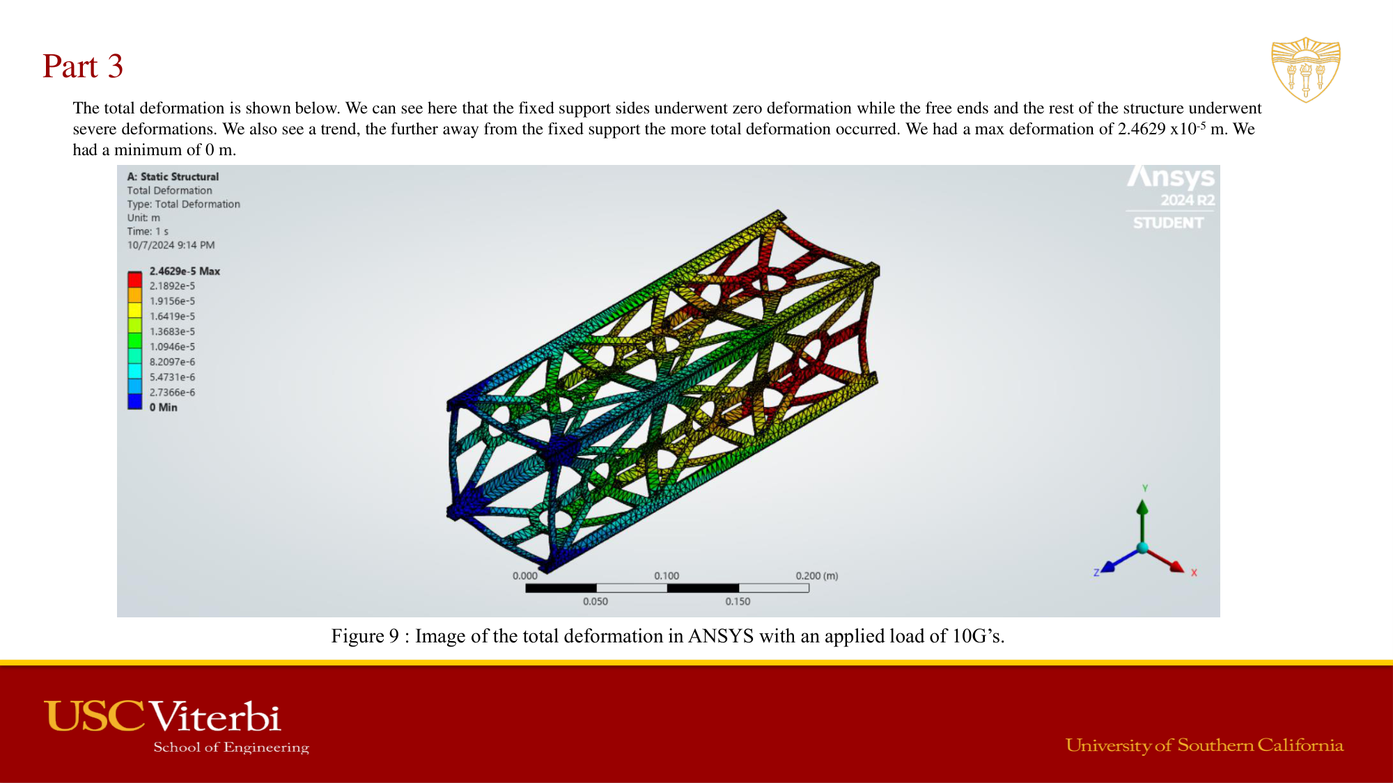
Applied ANSYS Workbench to simulate a satellite structure subjected to 10g launch acceleration loads. Covered aerospace failure modes including composite damage, bonded joint failures, fatigue, corrosion, BVID, and hail damage. Post-processed elastic strain contour plots and total deformation results to evaluate structural margins under worst-case launch loading.
AME 485 — Project 2 Full Report
Satellite structure FEA · 10g launch loads · ANSYS Workbench
Aircraft Fuselage — Cabin Pressure Differential FEA
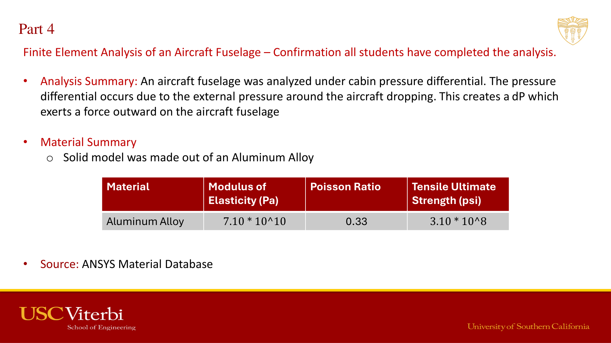
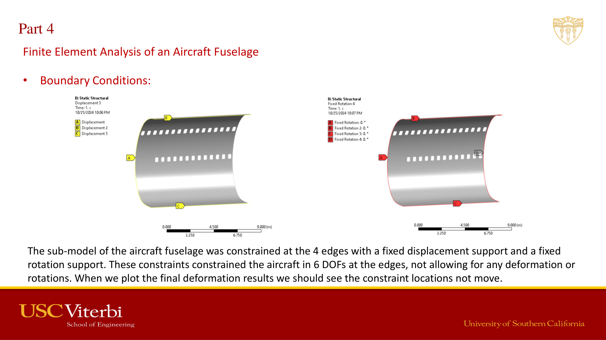
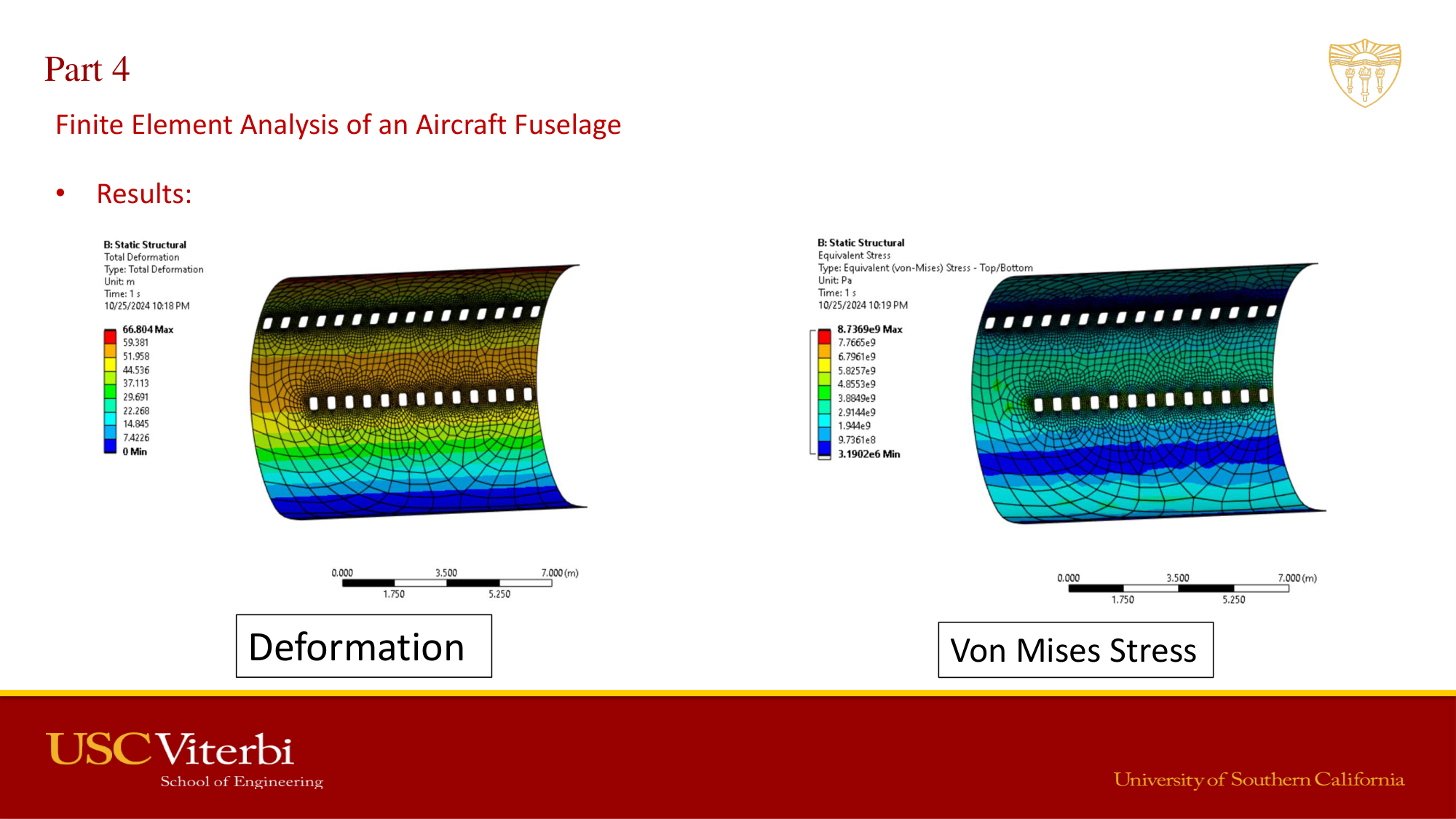
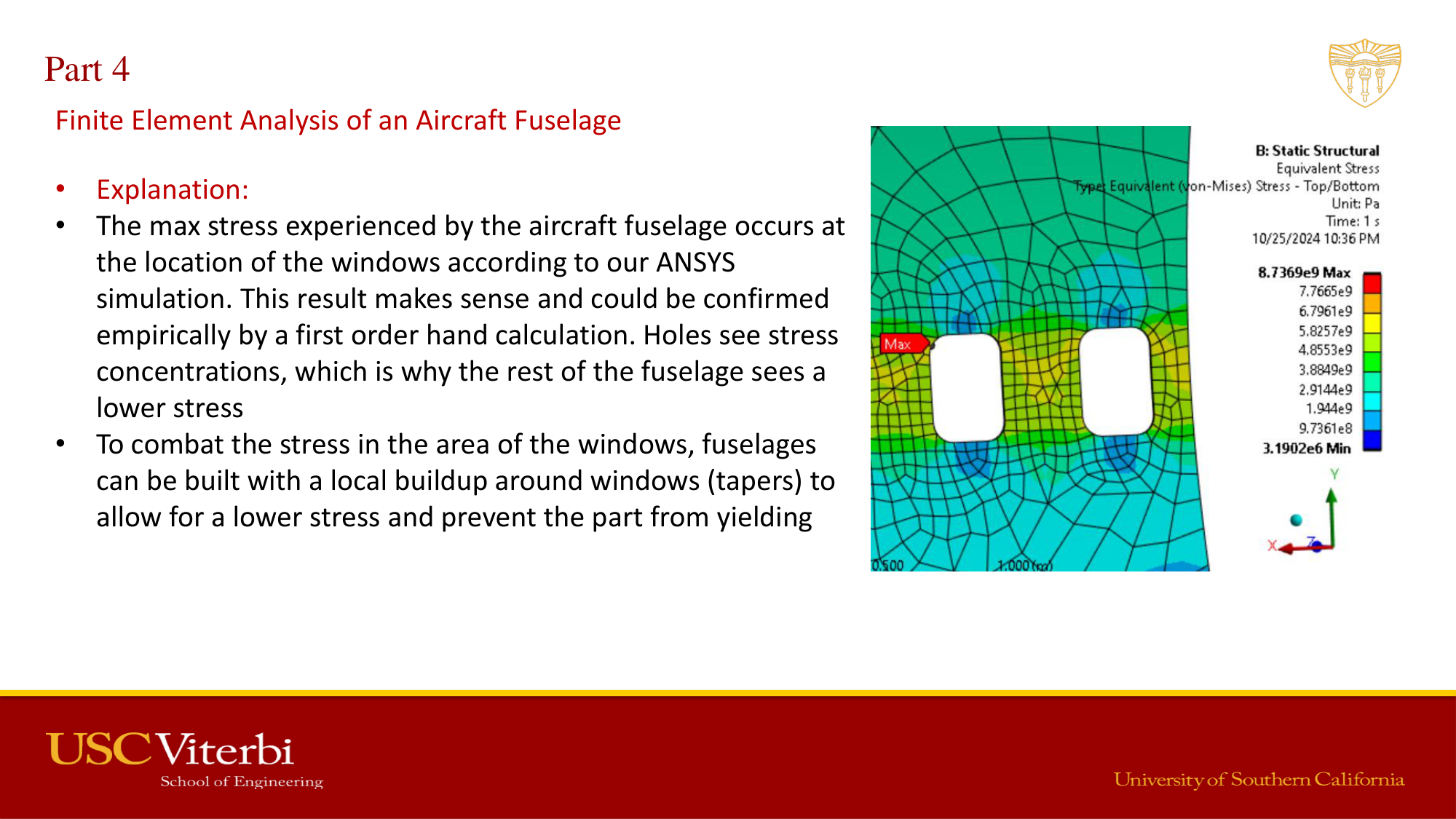
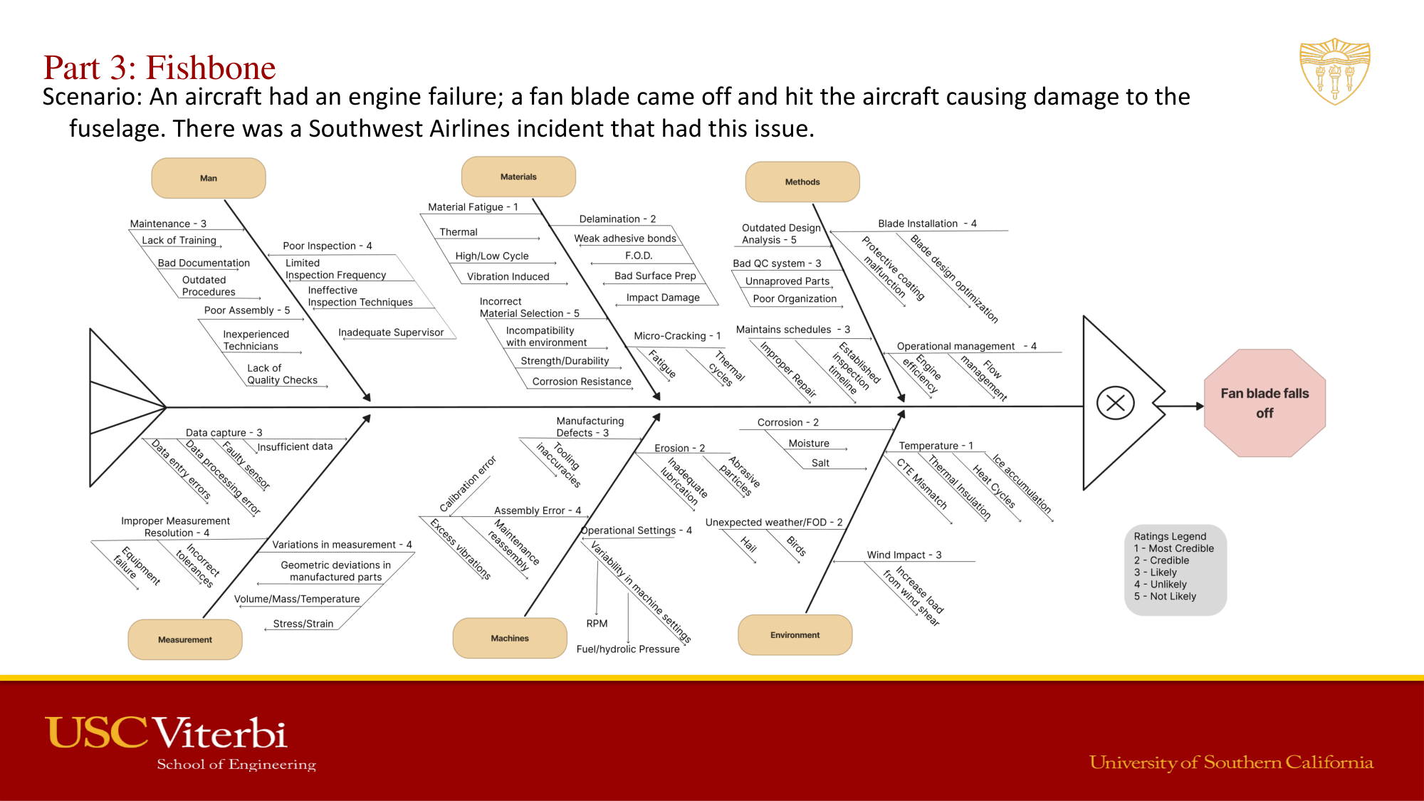
Analyzed failure modes in the James Webb Space Telescope and studied Challenger and Columbia disaster case studies using Fishbone (Ishikawa) diagrams and FMEA methodology. Performed ANSYS FEA on an aircraft fuselage section under cabin pressure differential loading — extracting von Mises stress, total deformation, and identifying window cutout stress concentrations.
AME 485 — Project 3 Full Report
Fuselage pressure differential FEA · Fishbone failure analysis · ANSYS
Valve Component FEA — Pressure-to-Failure Analysis
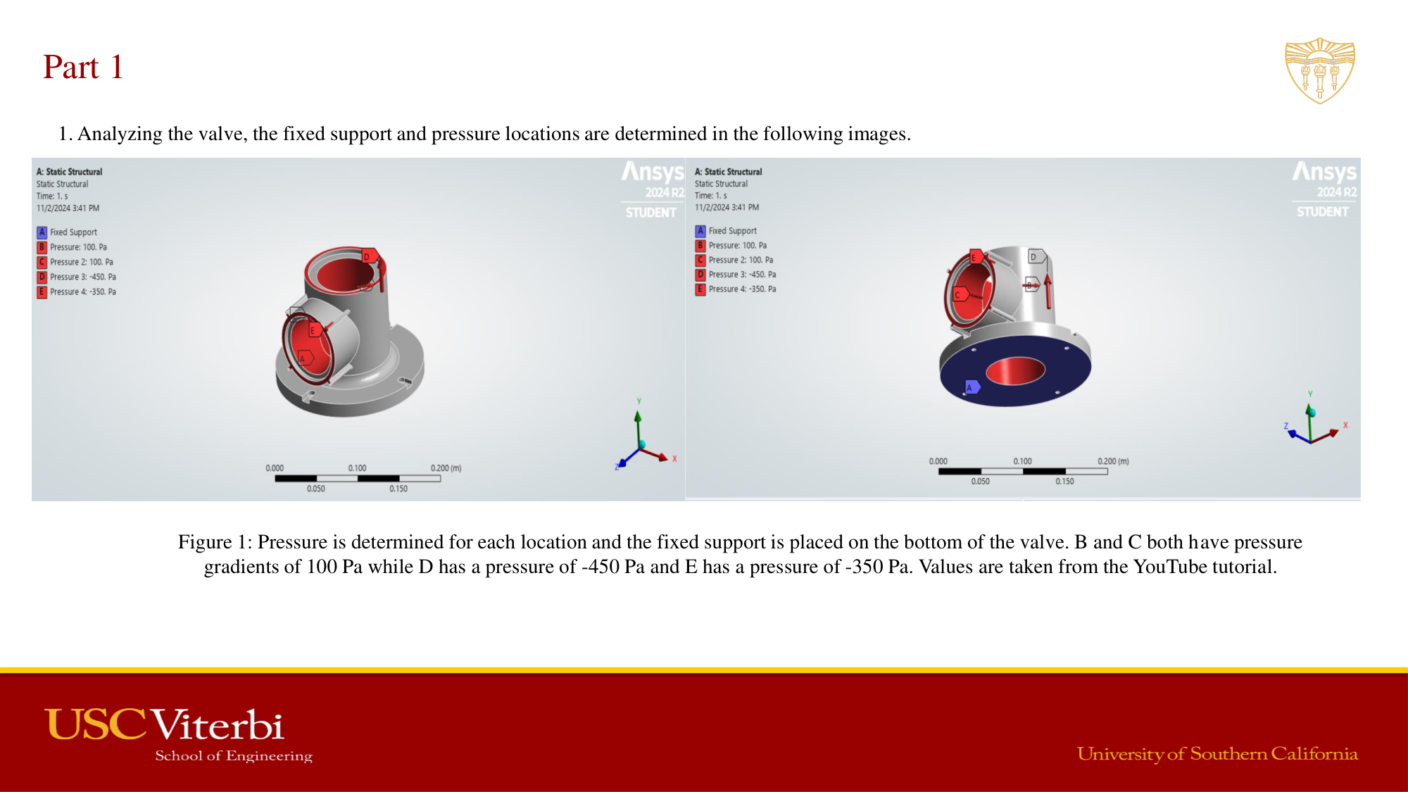
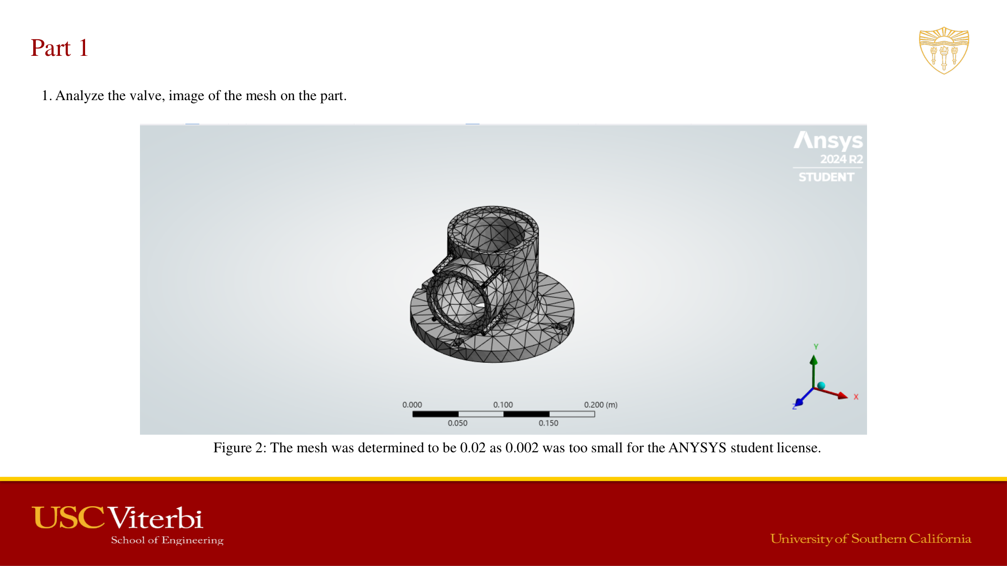
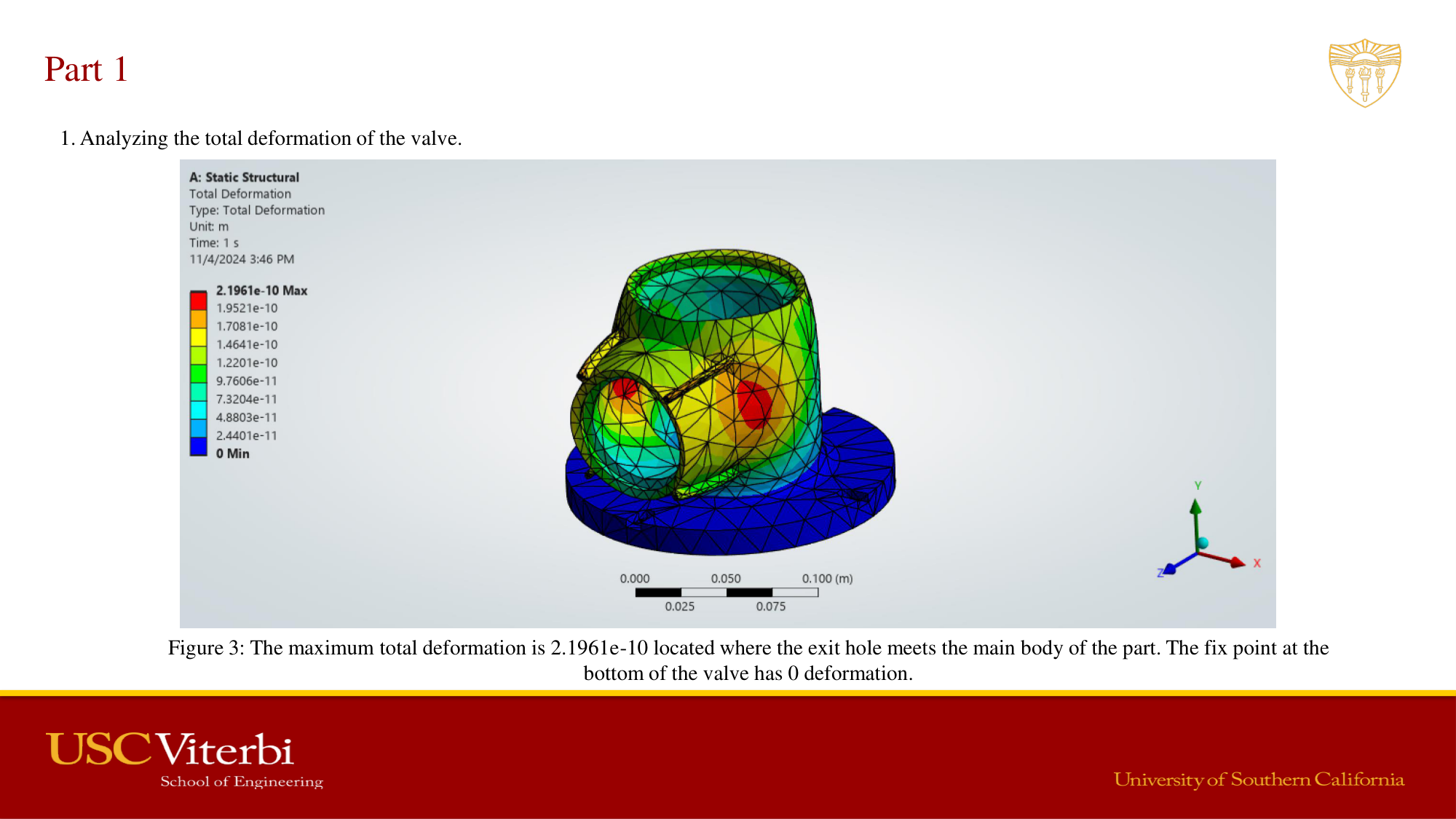
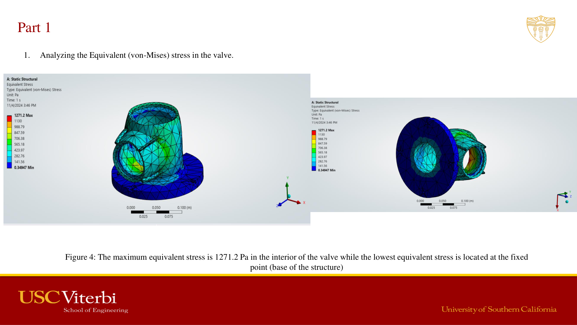
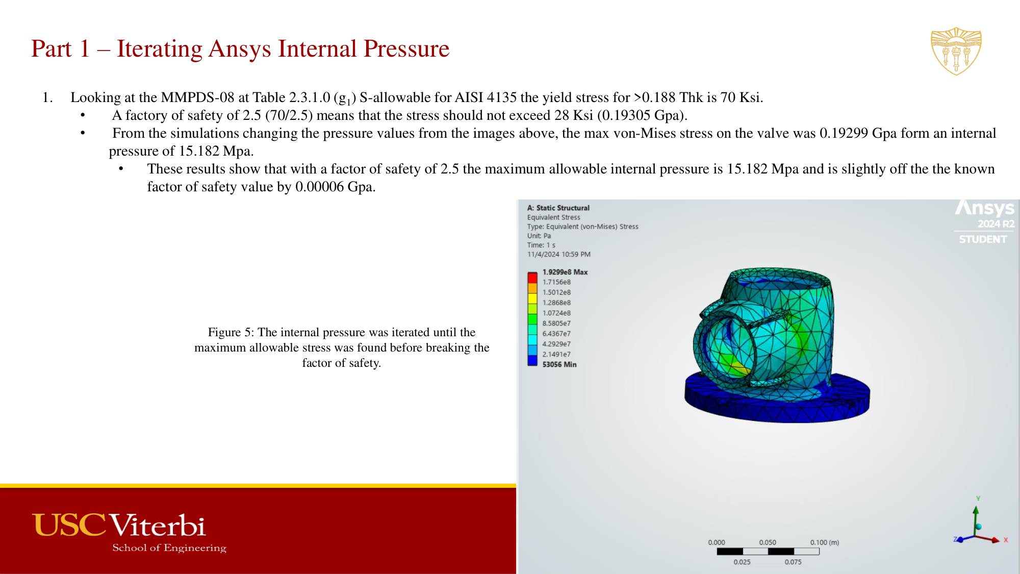
Performed iterative ANSYS structural analysis on a valve component subjected to increasing internal pressure loads. Meshed the geometry, applied boundary conditions, and evaluated total deformation and von Mises stress against MMPDS material allowables for AISI 4135 steel. Iterated load cases to determine the failure pressure and margins of safety using aerospace design factors.
AME 485 — Project 4 Full Report
Valve component pressure-to-failure FEA · AISI 4135 steel · ANSYS
Aircraft Wing Structural Analysis — ANSYS Static FEA
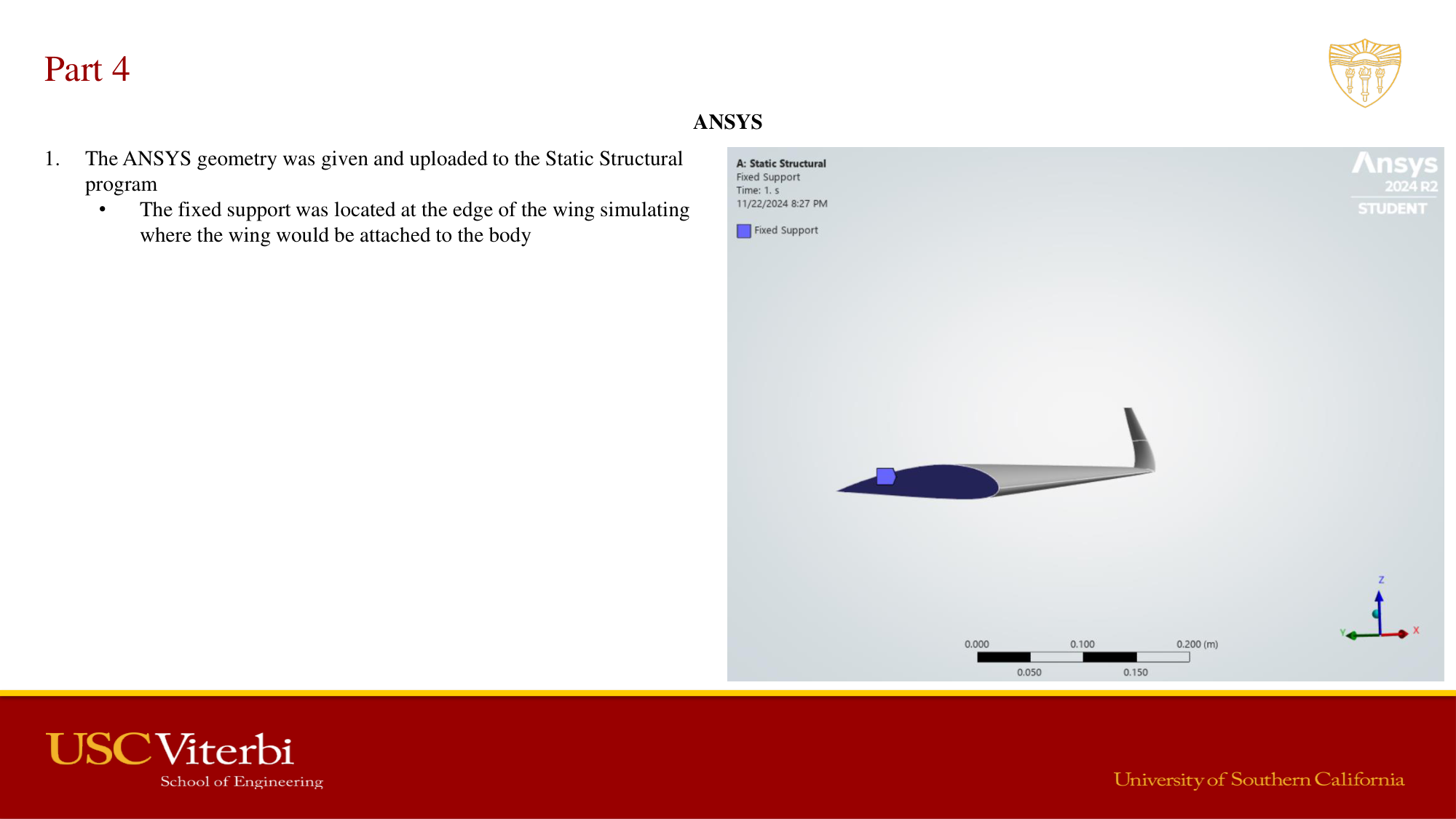
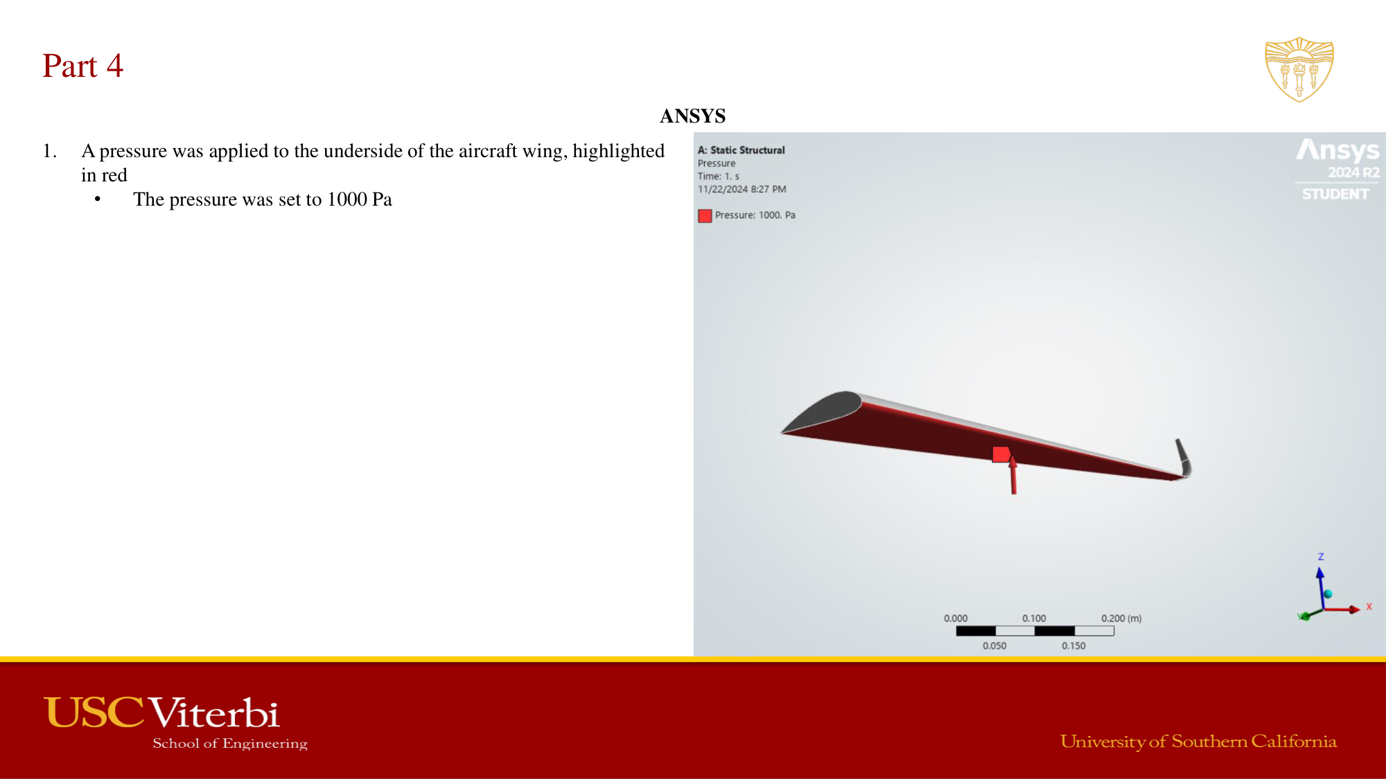
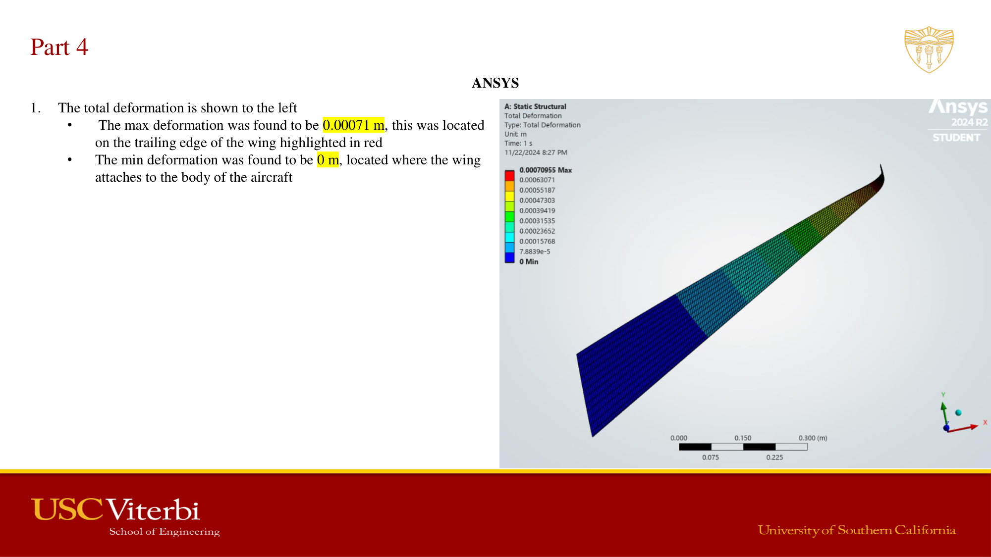
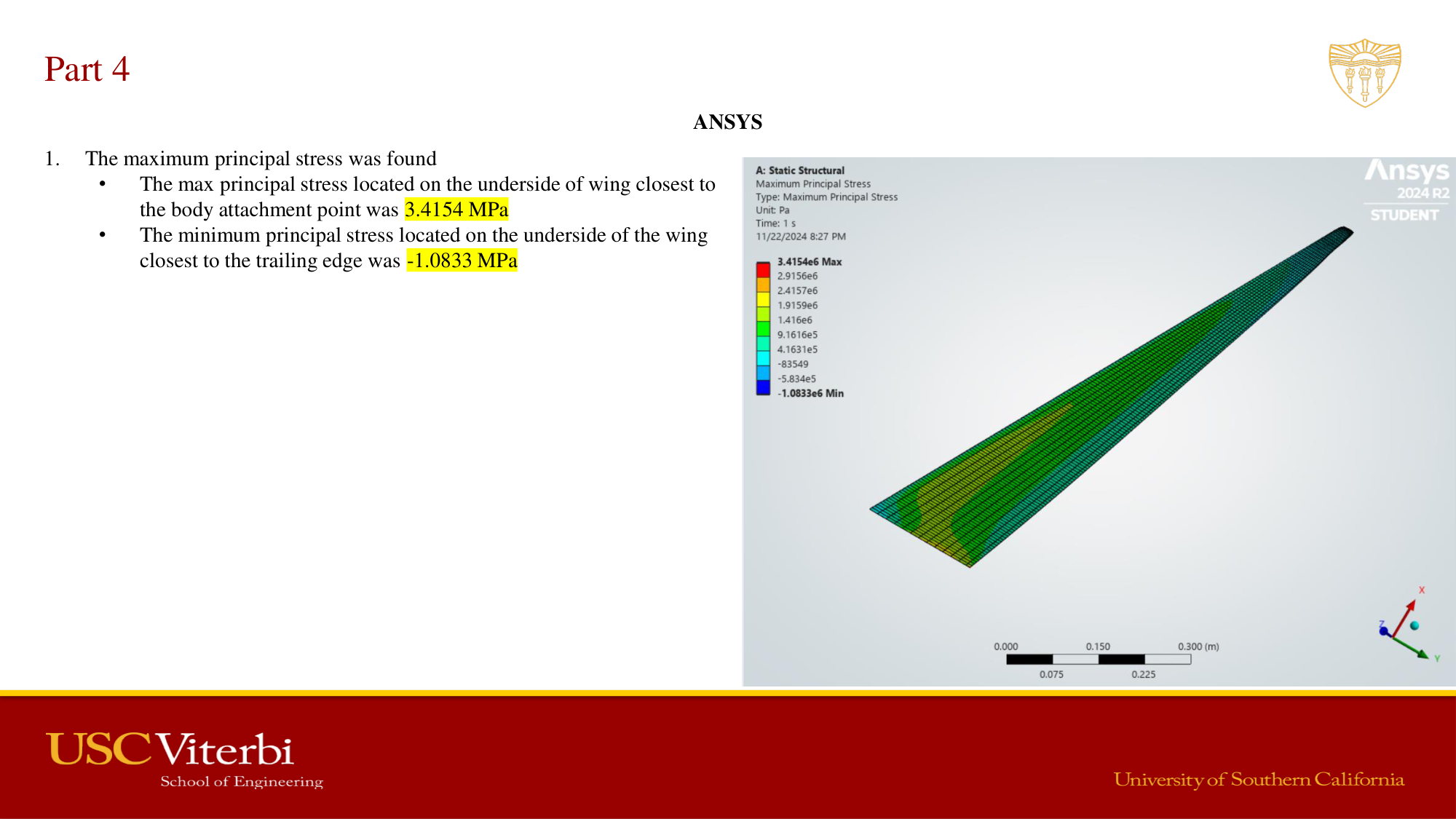
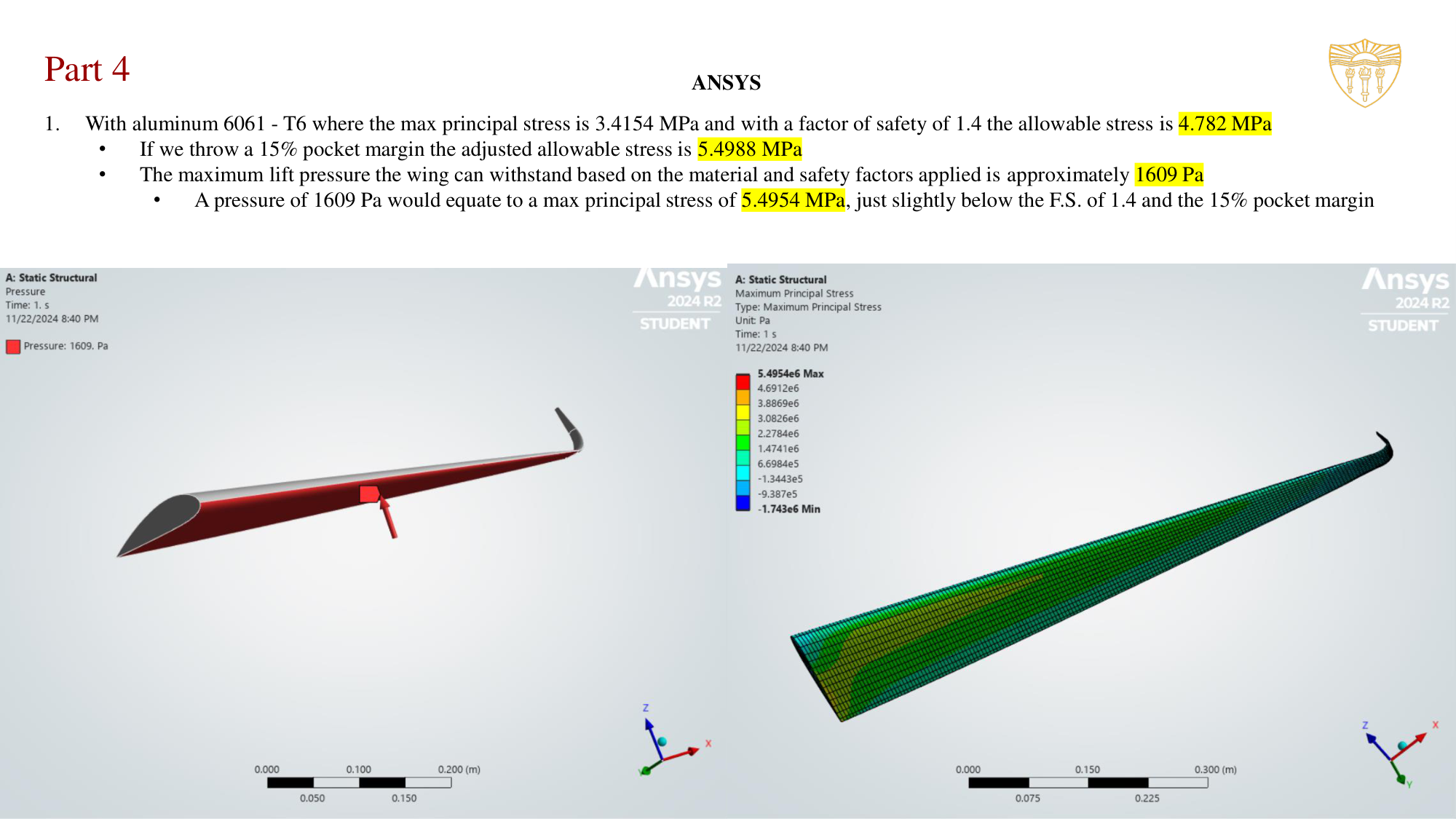
Performed static structural FEA in ANSYS on an aircraft wing under aerodynamic lift loading. The wing was fixed at the root to simulate its fuselage attachment, and a 1,000 Pa pressure was applied to the underside. The maximum total deformation was 0.00071 m (0.71 mm) at the trailing edge tip, and the maximum principal stress was 3.4154 MPa on the underside near the root. Applying a factor of safety of 1.4 and a 15% pocket margin raises the 1,000 Pa design load to a factored load of 1,609 Pa. A rerun at that load produced a maximum principal stress of 5.50 MPa, matching the linearly scaled hand calculation. Any candidate material must therefore have a strength of at least 5.50 MPa.
Documentation
AME 485 — Project 5 Full Report
Aircraft wing static structural FEA · ANSYS simulation data · Al 6061-T6 · Spring 2025