Project 16 · AME 308
3D CAD & Part Modeling — Siemens NX
AME 308 · Computer Aided-Design for Aero-Mechanical Systems · University of Southern California
Software
Siemens NX (Advanced)
Parts Modeled
Hairdryer · Bell Crank · Wheel Hub · Bracket · Link
Drawings
Multi-view sheets with GD&T
Analysis
Mass Properties · Static FEA
Solver
NX Nastran
Siemens NX is the primary CAD platform used throughout my engineering work. AME 308 built proficiency across the full NX workflow: parametric part modeling from constrained sketches through solid extrusions, revolves, blends, and boolean operations; engineering drawing production following ASME Y14.5 with GD&T; mass property extraction including inertia tensor and center of mass; and the complete CAD-to-FEA pipeline via NX Nastran. Parts ranged from simple extruded profiles to complex consumer-product geometry with compound surfaces.
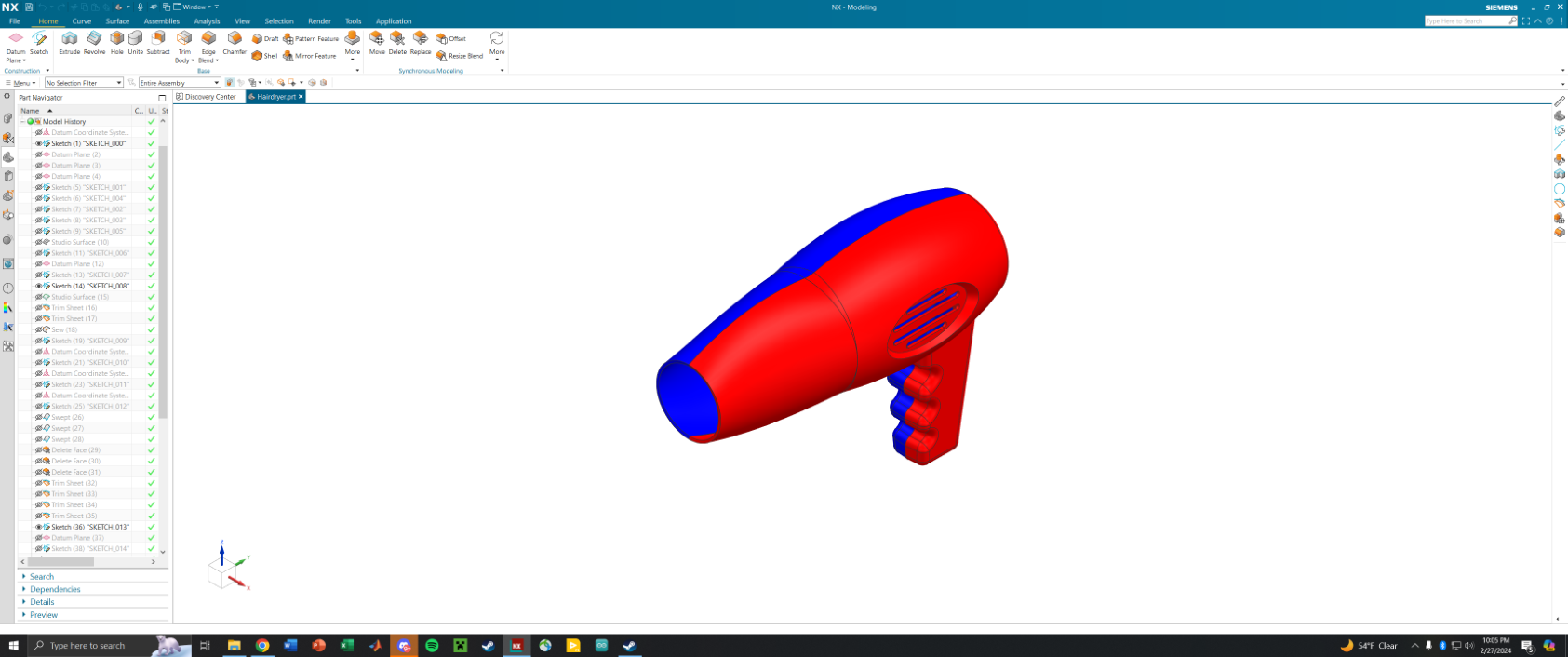
Solid Body Modeling — Complex to Simple
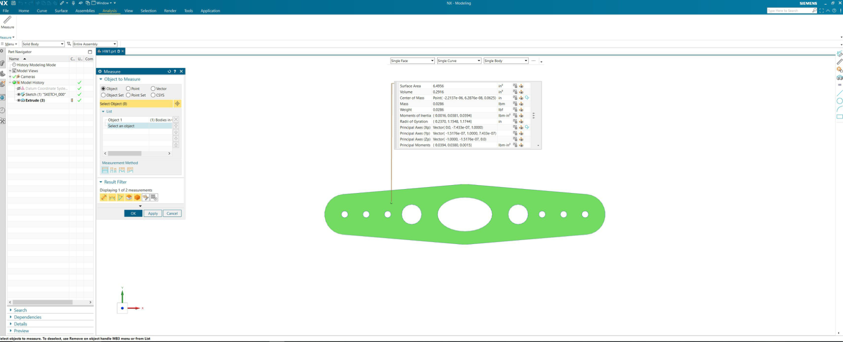
Every part was built from a fully constrained parametric sketch — all geometry driven by explicit dimensions and relations, with no under-constrained degrees of freedom. The hairdryer (HW6) is the most demanding model: the body required multiple sketches, a blended multi-section solid for the tapered nozzle, extruded vent grille slots, a swept handle grip, and mirrored geometry — all stitched into a single watertight solid body. Simpler assignments like the flat link (HW1) and bell crank plate (HW2) focused on constrained profiles, through-pockets, and fillets, with the NX feature tree fully defined and parametrically editable.
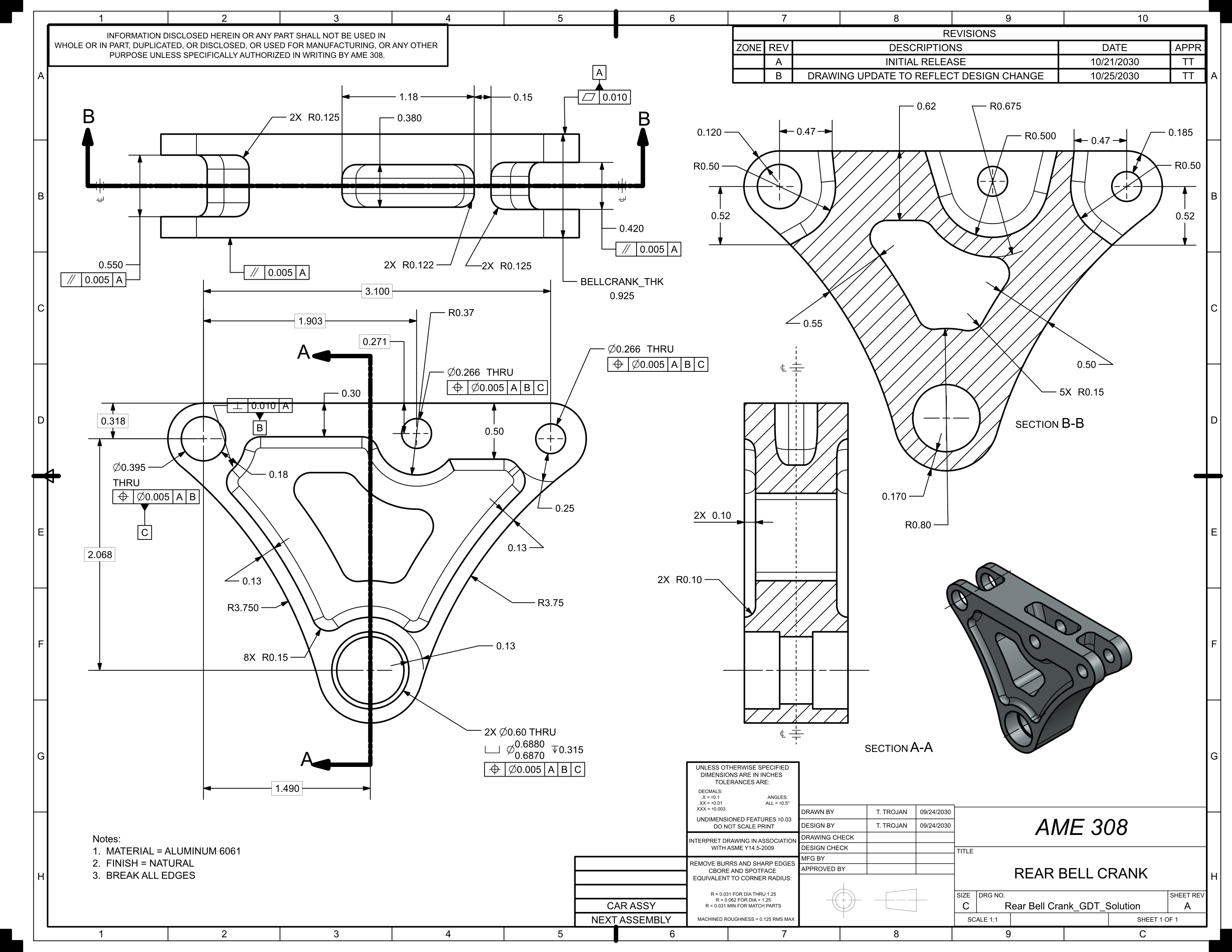
ASME-Standard Multi-View Drawings
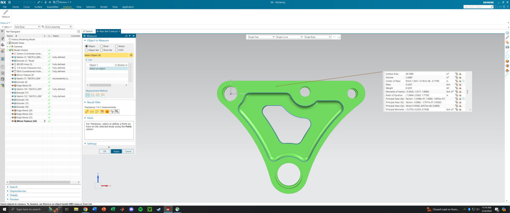
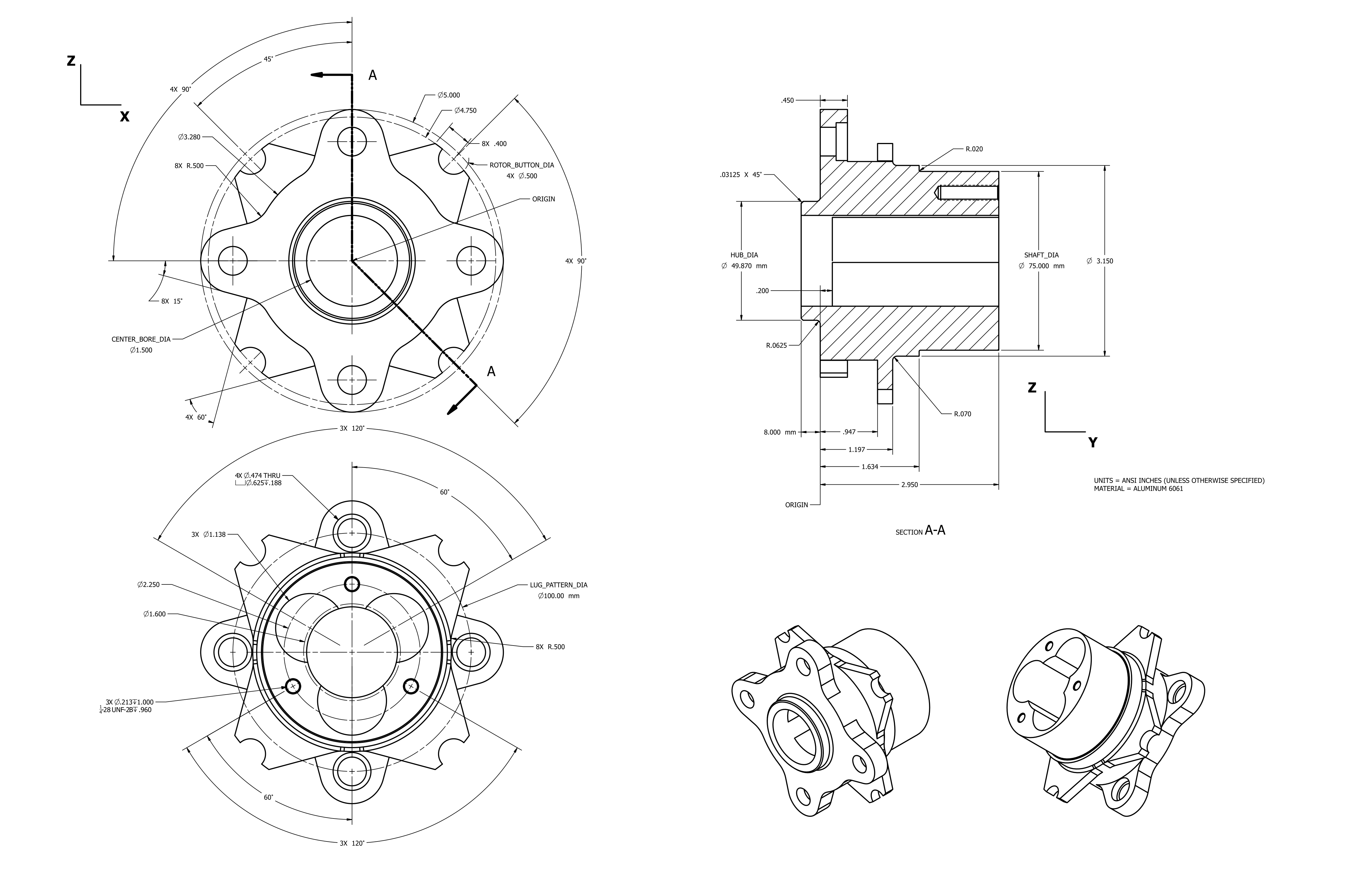
From each solid model, NX Drafting was used to produce formal engineering drawings following ASME Y14.5 conventions: principal orthographic views, section cuts, isometric views, complete dimensional callouts, tolerance notes, and title blocks with revision history. The Rear Bell Crank (HW7) is the most complete example — it includes full GD&T positional tolerance callouts (⌀0.0001 A|B|C datums), flatness and parallelism controls, Section A-A and Section B-B cuts, revision table, and material note (Aluminum 6061). The Wheel Hub (HW5) demonstrates complex circular geometry with bolt pattern, counterbore detail, and Section A-A through a rotational part.
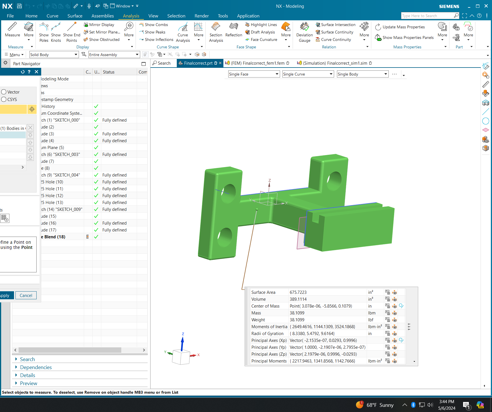
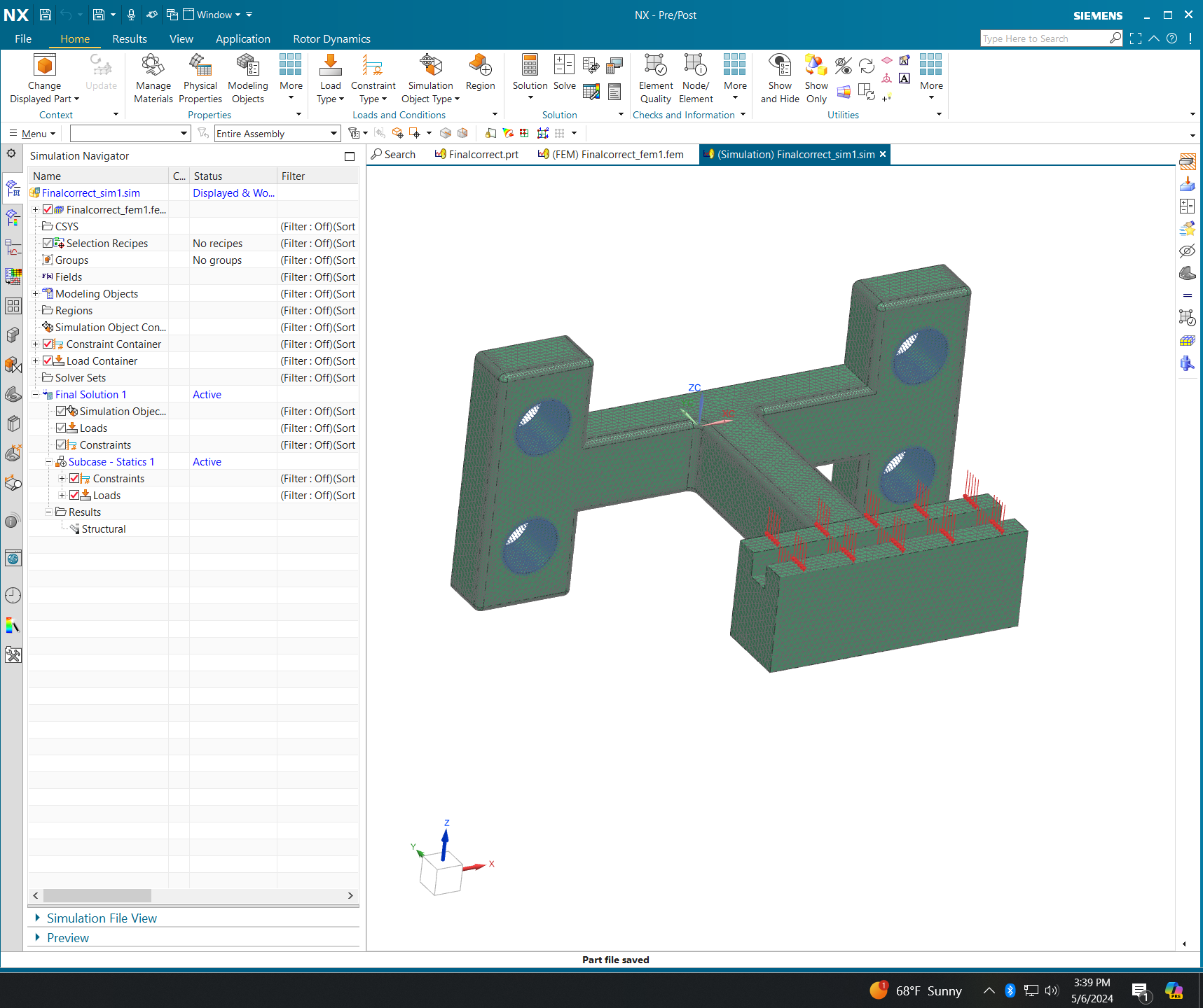
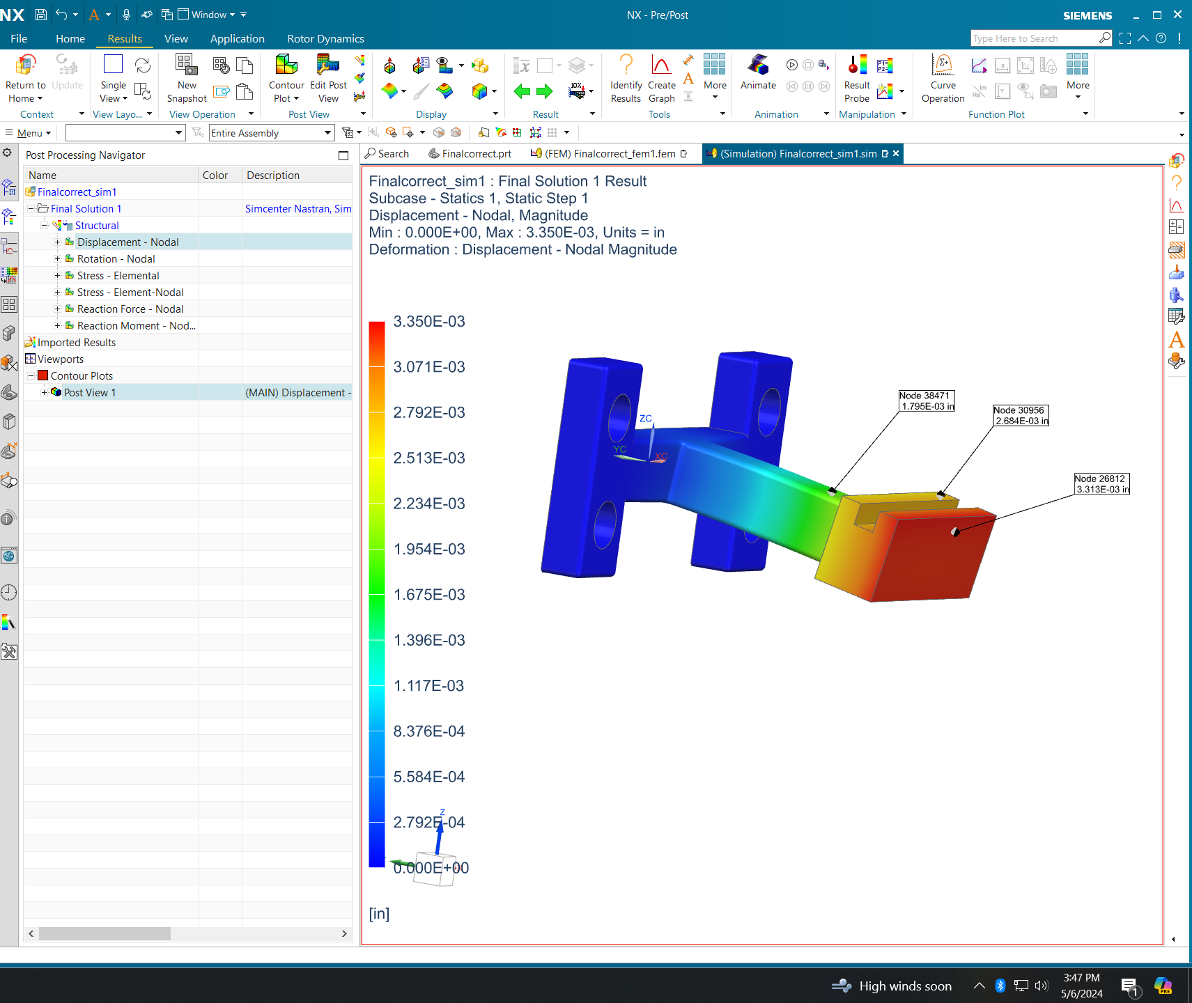
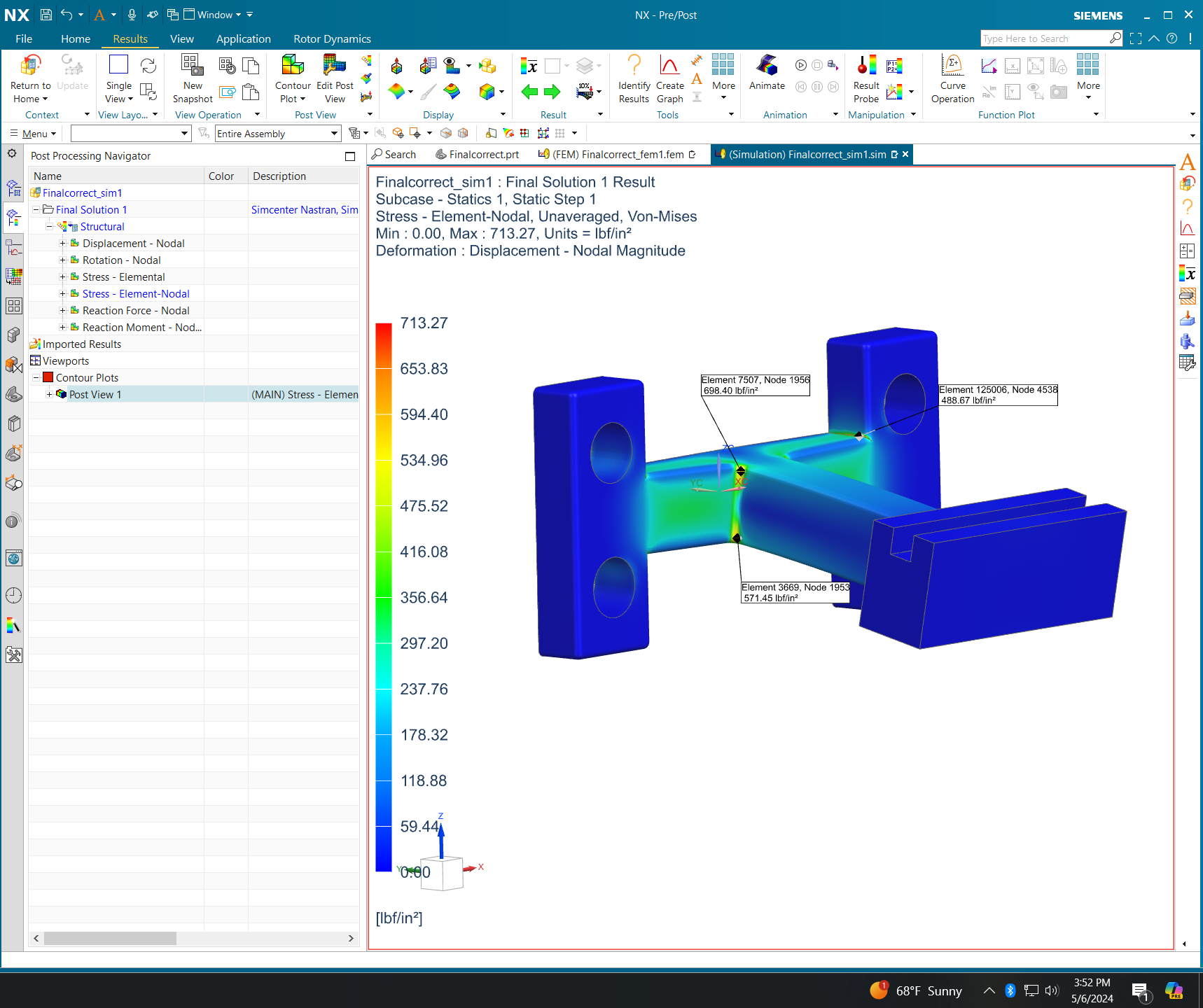
CAD-to-FEA Pipeline — Structural Bracket
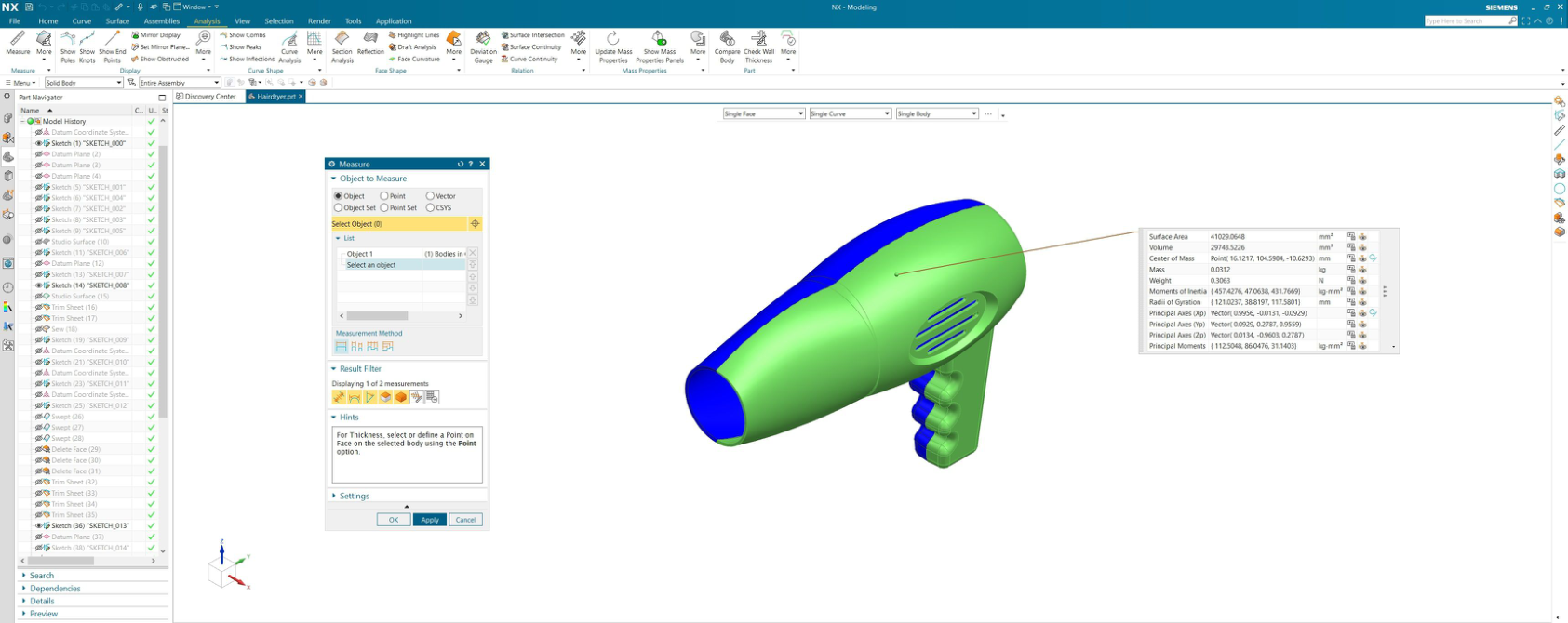
NX computes mass properties directly from the solid body — surface area, volume, center of mass (XYZ), total mass, and the full inertia tensor (principal moments and axis vectors). These values double as a model sanity check before any simulation is run.
The same geometry feeds directly into NX Nastran FEM setup: the solid is meshed with 3D tetrahedral elements, material properties are assigned, and boundary conditions are applied — fixed cylindrical constraints at the mounting holes, distributed load on the bearing face. The solved static results are post-processed as nodal contour plots.
For the full drone propeller FEA — 4-iteration mesh convergence study, 252k elements, 0.0451 mm tip displacement — see the AME 308 FEA page →